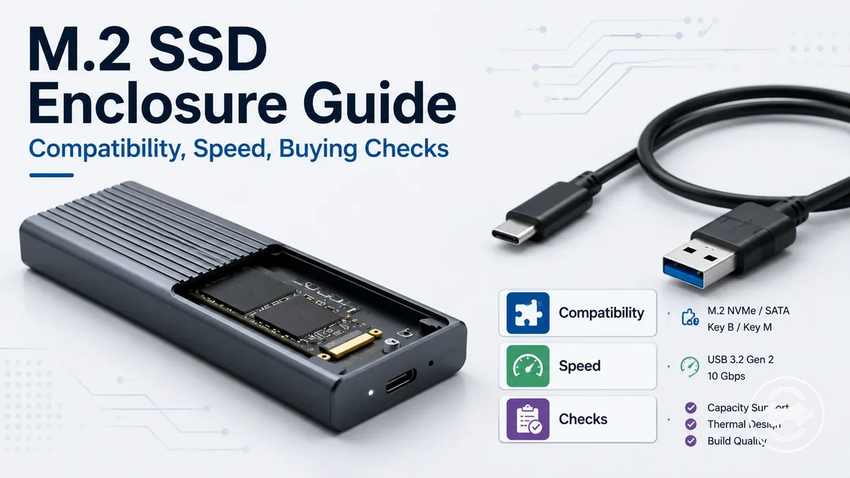
M.2 SSD enclosure guide for compatibility, performance, and buying fit
M.2 SSD enclosure refers to an external enclosure that lets an internal M.2 SSD connect to a host device as portable storage. It is a category-level decision topic because the right SSD enclosure depends on fit, connection, transfer speed expectations, and buying fit rather than on a product list.
An M.2 SSD enclosure should be checked first for compatibility before speed or features are judged. M.2 naming alone does not confirm whether an NVMe or SATA drive will work, whether the key type and drive length fit, or whether the USB-C connection can support the expected transfer speed. Real performance can vary by drive type, enclosure support, host port, cable, heat, and use case.
If you are reusing an internal M.2 SSD, adding portable storage, or comparing an external enclosure with another storage option, the safest starting point is compatibility-first evaluation. Thermal design, controller behavior, USB-C support, and feature trade-offs can then be judged against how the enclosure will actually be used.
What an M.2 SSD enclosure does for an internal drive
An M.2 SSD enclosure is an external housing and adapter that lets an internal M.2 SSD connect to another device. The enclosure body holds the drive and exposes it through an external connection. Its basic role is to convert an internal M.2 SSD into storage that a host device can access through a USB connection.
What an M.2 SSD enclosure does for an internal drive is present the installed SSD as external storage through a supported connection. For a broader explanation, see what an M.2 SSD enclosure does. The diagram below labels the enclosure body, bridge controller, external USB port, cable, and host device to show how the internal drive becomes an external device.
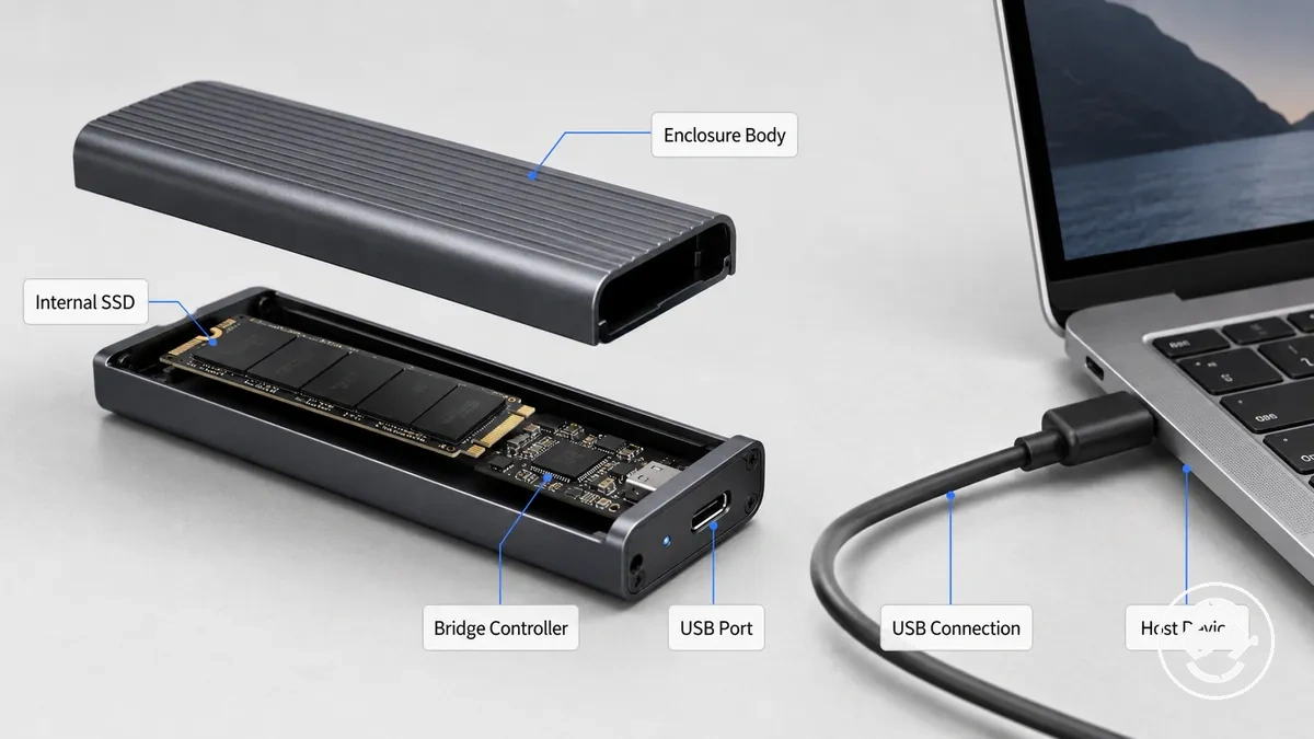
An M.2 SSD enclosure is not the same as a complete portable external SSD unless an internal drive is installed. It also does not automatically make every M.2 drive compatible or match the drive's advertised internal transfer speed. Compatibility and performance still depend on drive type, enclosure support, the bridge controller, and the connected host device.
M.2 SSD enclosure compatibility conditions
Compatibility depends on drive protocol, keying, physical length, connector fit, controller support, and the host connection. Checking these conditions first helps determine whether an M.2 SSD enclosure can recognize and use a drive before speed or feature comparisons become meaningful. Compatibility is the gate before evaluating performance or additional features.
M.2 SSD enclosure compatibility conditions should be verified before purchase or setup because similar labels do not always indicate the same protocol or enclosure support. For more detailed criteria, see M.2 SSD enclosure compatibility. The annotated image below highlights the visible fit conditions and shows how protocol support, keying, and M.2 length can influence successful detection or non-detection.
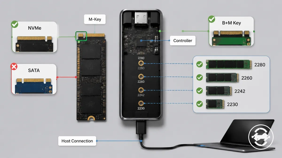
- Protocol support: Verify whether the enclosure supports NVMe, SATA, or both, or the drive may not be detected.
- Key type: Check whether the drive uses M-key or B+M key, because connector appearance alone does not confirm protocol support.
- M.2 length: Confirm support for 2230, 2242, 2260, 2280, or 22110, or the drive may not fit the available mounting position.
- Controller support: Ensure the enclosure controller supports the installed drive, as unsupported combinations can result in non-detection.
- Host connection: Verify the cable, port, and host connection because recognition depends on the complete connection path.
A drive may fit physically yet still fail to work if the protocol, controller support, or keying does not match. Dual-protocol enclosures can support more than one drive type, but visible labels, key shapes, or matching M.2 length alone do not guarantee compatibility.
Check protocol support, physical fit, and host connection before judging transfer speed or extra features. The checklist above provides the core conditions to verify before relying on enclosure support.
NVMe, SATA, and dual-protocol support
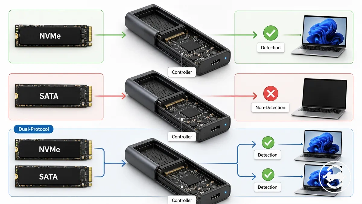
NVMe, SATA, and dual-protocol support determine whether an M.2 SSD enclosure can detect the installed drive. NVMe and SATA use different drive protocols, so the enclosure controller must support the same drive protocol as the SSD. Protocol support must match the installed drive before reliable detection can be expected.
| Drive protocol | Enclosure support needed | What happens if unsupported |
|---|---|---|
| NVMe | NVMe protocol support in the enclosure controller | The drive may result in non-detection. |
| SATA | SATA protocol support in the enclosure controller | The drive may not be detected even if it fits physically. |
| Dual-protocol | Explicit dual-protocol support in the enclosure controller | Support should be verified because dual-protocol capability cannot be assumed. |
Physical fit does not mean the drive protocol is supported, so a matching connector should not be treated as proof of compatibility. A dual-protocol enclosure can support both NVMe and SATA in some designs, but the enclosure specifications should be verified rather than assuming support from the enclosure label alone.
Key type, connector fit, and supported M.2 lengths
Key type, connector fit, and supported M.2 lengths determine whether an SSD can be seated and secured inside an enclosure. The key notch must align with the enclosure connector, while the M.2 length should match a supported mounting point and spacer position because enclosure layouts can vary by model. These visible fit checks determine whether the drive can seat correctly and remain securely retained after enclosure closure.
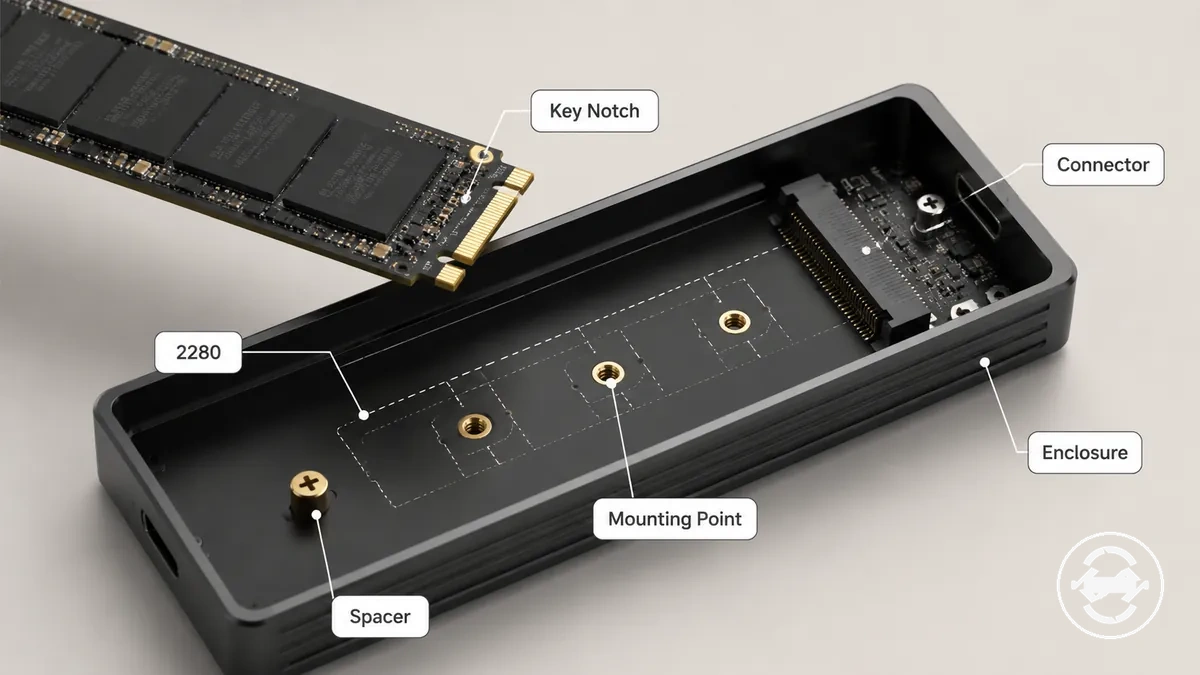
If the key notch, connector fit, or SSD length does not match the enclosure, installation may fail or the drive may not remain securely retained. The checklist below uses key type, connector fit, and supported M.2 lengths to verify whether the drive can sit and lock correctly.
- Key notch: Confirm that the SSD key type matches the enclosure connector so the drive can seat correctly.
- Connector fit: Check that the connector accepts the drive without forcing insertion, as a mismatch can prevent proper seating.
- M.2 length: Verify that the enclosure supports the SSD length, such as 2280, because supported sizes vary by model.
- Mounting point and spacer: Ensure the mounting point and spacer align with the SSD length to provide secure retention.
- Enclosure closure: Confirm that the installed SSD allows normal enclosure closure, because incorrect physical fit may affect retention or prevent the enclosure from closing properly.
Speed limits that shape real transfer performance
Real transfer speed depends on the slowest relevant part of the drive, enclosure, cable, port, and workload chain rather than a single specification. The SSD, enclosure controller, USB-C connection, cable rating, host port, and workload each contribute to real performance. In practice, transfer speed follows the slowest-link principle.
Advertised interface labels describe capability, but they do not determine real throughput on their own. A fast SSD may still perform below its potential if the enclosure controller, USB 3.2 or Thunderbolt connection, cable rating, or host port introduces a lower speed ceiling. File size, thermal state, and sustained transfer workloads can also influence results, so interface labels should be distinguished from real transfer behavior.
When copying large files, many small files, or running long transfer sessions, different parts of the connection chain can become the limiting factor. USB-C connector shape alone does not define the available speed because cable rating and host port capability also influence the speed ceiling. For more detail on these relationships, see ports and speed limits. The table below summarizes the main attributes that shape real transfer performance.
| Part of the chain | Attribute to check | Possible limit | Effect on real transfer performance |
|---|---|---|---|
| Drive interface | SSD capability | Drive interface support | May limit available throughput. |
| Enclosure controller | Controller capability | Controller performance limit | Can reduce effective transfer speed. |
| Cable | Cable rating | Lower-rated cable | May reduce the available speed ceiling. |
| Host port | USB-C, USB 3.2, or Thunderbolt support | Port capability | Real performance depends on the connected port. |
| Thermal state | Heat during use | Sustained operating temperature | May influence sustained transfer behavior. |
| Workload | File size and transfer pattern | Mixed or sustained workload | Real throughput can vary with the workload. |
Real transfer speed should be evaluated across the complete connection path instead of a single interface label. Sustained transfer performance depends on the combined behavior of the drive, enclosure, cable, host port, thermal state, and workload, so results can vary during longer workloads.
USB-C, USB 3.2, USB4, and Thunderbolt speed ceilings
USB-C, USB 3.2, USB4, and Thunderbolt describe different aspects of a connection, so they should not be treated as interchangeable speed labels. USB-C identifies the connector shape, while USB 3.2, USB4, and Thunderbolt identify connection standards that may support different speed ceilings. Expected enclosure performance depends on the connection standard, cable requirement, enclosure support, and host support rather than the USB-C connector shape alone.
A common misconception is that every USB-C port provides the same transfer capability. In practice, the connection label is only one part of the performance chain because cable requirement, enclosure support, and host support must also align. The table below compares these labels as a guide to possible speed ceilings rather than guaranteed performance.
| Connection label | What it may indicate | What else must match | Performance implication |
|---|---|---|---|
| USB-C | Connector shape | Port standard, cable requirement, and host support | Does not indicate a specific speed ceiling on its own. |
| USB 3.2 | USB connection standard | Compatible enclosure, cable, and host support | Performance depends on end-to-end support. |
| USB4 | USB connection standard | USB4-compatible enclosure, cable, and host support | May support a higher bandwidth ceiling when the complete chain is compatible. |
| Thunderbolt | Thunderbolt connection standard | Thunderbolt-compatible enclosure, cable, and host support | Expected enclosure performance depends on complete compatibility across the connection chain. |
Drive speed, enclosure controller, cable, and host-port effects
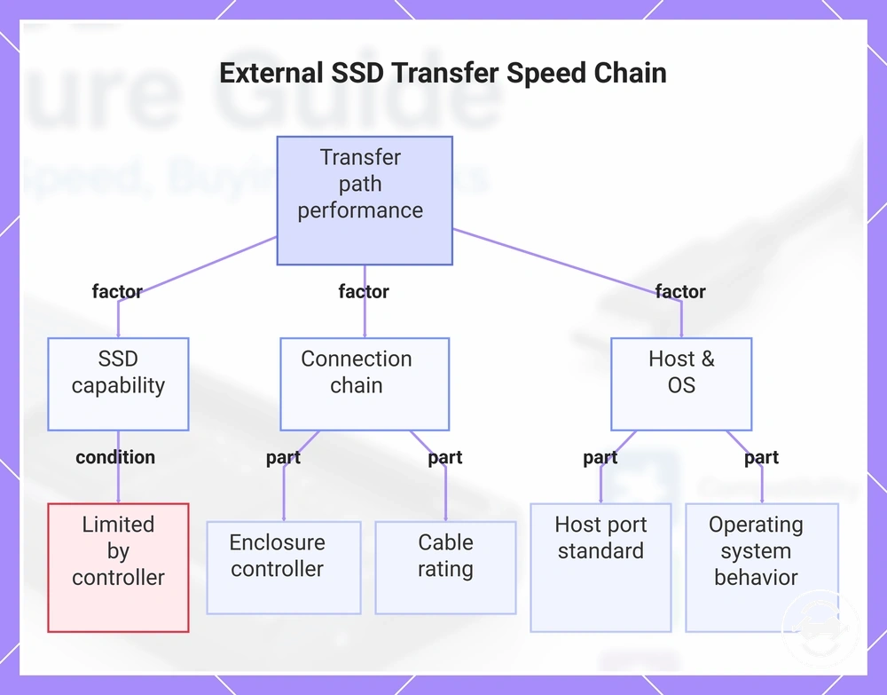
Real performance depends on the complete transfer path rather than SSD capability alone. The enclosure controller, cable rating, host port, and operating system can each influence throughput and stability, so a faster SSD does not necessarily produce faster transfers. In practice, the slowest part of the speed chain controls the overall result.
When a high-capability SSD is connected through components with lower capabilities, throughput may be limited before the drive reaches its potential. The relationships below show how each part of the chain can affect performance under different conditions.
- SSD capability: Higher drive capability → if the enclosure controller supports a lower performance level → throughput may be limited by the controller.
- Enclosure controller: Bridge chip capability → if it is lower than the SSD or host port capability → the controller may determine effective throughput or stability.
- Cable rating: Supported connection capability → if the cable rating is below the supported port standard → available throughput may be reduced.
- Host port: Port standard → if the host port supports a lower performance level than the enclosure → the host port may become the limiting part of the transfer path.
- Operating system: Device recognition and file transfer behavior → when configuration or support differs → throughput or stability may vary during file transfers.
If a fast SSD is paired with an enclosure, cable, or host port that supports a lower performance level, the overall transfer result typically follows the capability of the weakest part in the chain.
This chart shows the key components and conditions that determine the real transfer speed of an external SSD, highlighting how the weakest part in the chain affects overall performance.
Heat behavior during sustained transfers
Heat during sustained transfers is common, but the level of risk depends on enclosure design, SSD workload, airflow, and thermal contact rather than warmth alone. An aluminum body can become warm as it transfers heat away from internal components, while prolonged SSD workload may increase heat buildup over time. Normal exterior warmth is different from symptoms that suggest further investigation.
When heat increases during long file transfers, checking the enclosure conditions before assuming a fault is usually the safer approach. Thermal pad contact can help move heat from the SSD to the aluminum body, while restricted airflow or poor thermal contact may reduce passive cooling effectiveness. Longer sustained transfers can place a higher load on the SSD controller, which may contribute to throttling under some conditions. Heat behavior depends on SSD workload, thermal contact, and enclosure design.
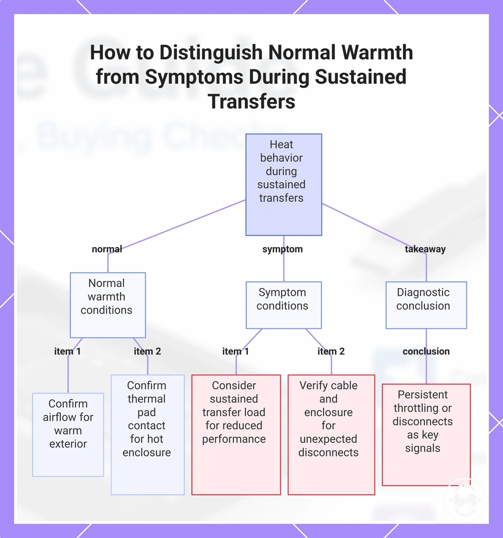
If transfer performance drops noticeably or unexpected disconnects occur during extended file transfers, those symptoms may warrant additional checks rather than being treated as normal warmth. For more detailed guidance, see heat and thermal issues. The checklist below helps distinguish common warmth from symptoms that deserve closer attention.
- Warm exterior: Likely condition: heat is spreading through the enclosure body. Next check: confirm airflow is not restricted during sustained transfers.
- Reduced transfer performance: Likely condition: SSD workload may contribute to throttling. Next check: consider whether long sustained transfers are increasing heat buildup.
- Unexpected disconnects: Likely condition: heat, cable stability, or another connection issue may be involved. Next check: verify cable connection and enclosure stability before assuming a hardware fault.
- Hot enclosure after extended use: Likely condition: passive cooling is transferring heat to the aluminum body. Next check: confirm the thermal pad makes proper contact with the SSD.
Warmth alone does not necessarily indicate a defect. Persistent throttling or repeated disconnects are more useful diagnostic signals than exterior temperature by itself, and their significance depends on workload and operating conditions.
This chart categorizes the checklist conditions for heat behavior during sustained transfers into normal warmth, symptoms to investigate, and a key diagnostic conclusion.
Thermal pads, aluminum bodies, and passive cooling limits
A thermal pad and aluminum body are designed to improve heat transfer from the SSD, but they do not eliminate all thermal limits. The thermal pad relies on suitable contact pressure and thermal contact to create an effective cooling path, while the aluminum body spreads SSD heat output across the enclosure through passive cooling. These materials help transfer heat rather than remove it completely.
A common misconception is that better materials prevent throttling in every workload. The comparison below shows how each cooling element supports heat transfer while remaining subject to SSD heat output, workload, enclosure design, and contact quality. Passive cooling can improve sustained performance or comfort, but its effect remains conditional rather than guaranteed.
| Cooling element | What it helps | Limit to mention |
|---|---|---|
| Thermal pad | Improves heat transfer by creating thermal contact between the SSD and the aluminum body. | Effectiveness depends on suitable thickness and contact pressure. |
| Aluminum body | Spreads heat across the aluminum shell to support passive cooling. | The enclosure may still become warm during sustained workloads. |
| Passive cooling | Helps dissipate SSD heat output without active cooling. | High SSD workload can still contribute to throttling under some conditions. |
Throttling, disconnects, and heavy-write use cases
When transfer speed drops or the connection becomes unstable during heavy writes, the underlying cause may differ depending on the symptom. Sustained workload can contribute to heat buildup and throttling, while disconnects may instead relate to cable instability, power delivery, or controller behavior. Separating slowdown, disconnects, and normal pauses helps avoid incorrect diagnosis.
During sustained write load, compare the observed symptom before assuming the enclosure is faulty. Use the checklist below to distinguish the likely condition, the next check, and what the outcome may indicate. Heavy writes should be assessed with conditional checks rather than a single assumed cause.
- Symptom: Gradual slowdown during heavy writes. Likely condition: Heat buildup may contribute to throttling. Next check: Observe whether the slowdown begins after a sustained workload. What it means: Performance may improve when workload or temperature conditions change.
- Symptom: Unexpected disconnects. Likely condition: Cable instability, power delivery, or controller behavior may be involved. Next check: Verify cable connections and try another compatible port if available. What it means: The symptom does not necessarily indicate an enclosure fault.
- Symptom: Brief pauses during large transfers. Likely condition: Controller behavior or sustained write management may affect transfer flow. Next check: Check whether the transfer resumes without repeated disconnects. What it means: A temporary pause does not necessarily indicate hardware failure.
- Symptom: Repeated slowdown and disconnects together. Likely condition: More than one factor may be contributing. Next check: Review sustained workload, heat buildup, cable stability, and power conditions together. What it means: Multiple symptoms usually require broader troubleshooting instead of a single assumed cause.
Usability features that affect daily handling
Usability features affect how easy, durable, portable, and comfortable an M.2 SSD enclosure feels during repeated use. Convenience features should be judged by the intended use case because the most practical enclosure design for frequent drive changes may differ from one intended for occasional storage. Daily handling depends on how the enclosure design matches the expected use.
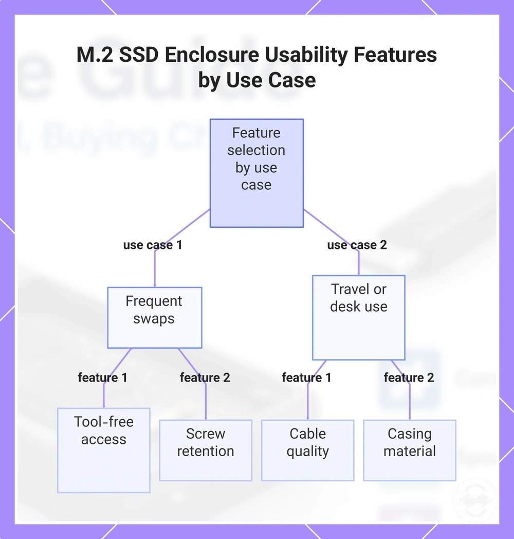
When drives are swapped regularly, tool-free access and reliable screw retention can reduce installation effort and make repeated handling more convenient. For one-time installation, these features may be less important than cable quality, casing material, portability, and durability during everyday use. Frequent swaps and one-time setup benefit from different usability priorities.
Repeated handling, travel, or long-term desk use can make small design differences more noticeable over time. Thermal pad handling, cable quality, portability, and casing material may influence convenience, while their value depends on how often the enclosure is opened or moved. The checklist below compares usability features with the situations where they may have the greatest decision effect.
- Tool-free access: Better suited to frequent swaps because it can reduce installation effort during repeated drive changes.
- Screw retention: Helpful for frequent swaps by reducing the chance of losing small fasteners during repeated installation.
- Thermal pad handling: More relevant when the enclosure is opened multiple times, as careful handling can help maintain thermal contact.
- Cable quality: Worth greater attention for travel use or frequent reconnection because repeated handling may place more stress on the cable.
- Casing material: May influence durability and daily handling comfort, depending on travel use or desk-based storage.
- Portability and LED indicators: Portability may matter more for travel, while LED indicators can provide simple activity feedback during desk storage or occasional backup use.
Usability features should be selected according to the expected handling pattern. Match convenience features to frequent swaps, travel use, desk-based storage, or occasional backup use instead of treating every feature as equally valuable.
This chart compares the most important usability features for frequent drive swaps versus travel or desk-based use.
Tool-free access versus screw-based retention
Tool-free access and screw-based retention should be compared by handling needs rather than treated as universal quality levels. The opening mechanism influences assembly effort, repeated access, thermal pad placement, and potential loose-fit risk, but the practical outcome depends on the enclosure design and user handling. The better design depends on how often the enclosure is opened.
For frequent drive changes, tool-free access may reduce assembly effort and simplify repeated access, while screw-based retention may suit users who rarely reopen the enclosure. The comparison below contrasts frequent swapping with set-and-forget use instead of presenting either design as a universal winner.
| Design choice | Handling trade-off | Best use case |
|---|---|---|
| Tool-free access | Can reduce assembly effort and improve repeated access, although loose-fit risk and thermal pad placement still depend on the enclosure design. | Frequent drive changes and repeated access. |
| Screw-based retention | May require more assembly effort, while handling characteristics, retention strength, and thermal pad placement continue to depend on the enclosure design. | Set-and-forget use or infrequent drive removal. |
Body material, cable support, portability, and durability
Body material, cable support, portability, and durability should be evaluated together because they influence everyday handling rather than acting as standalone quality signals. An aluminum body and a plastic body each involve different handling trade-offs, while cable support, connector strength, and an included adapter can affect convenience, heat feel, and long-term reliability. The most suitable combination depends on handling conditions, travel use, and how the enclosure is used over time.
For travel use, size, weight, protective fit, and cable support may become more important than body material alone. For desk-based use, portability may matter less than connector strength and consistent cable support. The trade-offs below help distinguish travel-focused handling from stationary use.
- Option: Aluminum body. Attribute: More rigid enclosure shell with a different heat feel. Trade-off: Durability and portability depend on the complete enclosure design. Best use case: Regular travel or repeated handling.
- Option: Plastic body. Attribute: Often lower in weight. Trade-off: Handling characteristics and durability depend on the casing material and construction. Best use case: Occasional travel or desk-based storage.
- Option: Cable support. Attribute: Cable type, connector strength, and included adapter. Trade-off: Long-term reliability depends on the complete connection rather than a single accessory. Best use case: Frequent reconnection or use with multiple compatible devices.
- Option: Protective fit. Attribute: Enclosure size and protective design. Trade-off: Additional protection may increase overall size or weight. Best use case: Travel use where the enclosure is carried regularly.
- Option: Compact enclosure. Attribute: Smaller size and improved portability. Trade-off: Portability should be balanced with durability and handling needs. Best use case: Users who move the enclosure frequently instead of leaving it on a desk.
Buying checks for matching an enclosure to your drive and use case
Buying checks should match the enclosure to the installed drive and the intended workload before comparing convenience features. Compatibility depends on drive protocol, M.2 length, key type, speed standard, host port, and thermal design rather than a single specification. Fit comes before features.
Choosing an enclosure without matching the main criteria can reduce purchase suitability even when the drive appears to fit physically. Use the checklist below to compare compatibility, performance expectations, and handling needs before making a decision. For additional decision criteria, see the buying checklist.
- Drive protocol: Verify enclosure support for the installed drive protocol because recognition depends on protocol compatibility.
- M.2 length: Verify supported M.2 length because mounting positions vary by enclosure design.
- Key type: Verify key type and connector fit because physical seating depends on key alignment.
- Speed standard: Verify the enclosure speed standard because performance expectations depend on the supported transfer path.
- Host port: Verify host port support because the connected device can limit real performance.
- Thermal design: Verify thermal design for sustained workload needs because heat behavior can vary with use.
- Access method: Verify whether tool-free access or screw retention suits the handling pattern because frequent swaps and one-time setup have different priorities.
- Material and cable support: Verify material, cable support, and connector strength because portability and durability depend on the complete design.
- Use case: Verify the intended use case because value depends on backup, file transfer, travel, or frequent-swap needs.
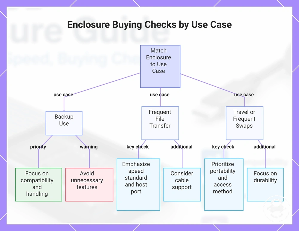
For backup use, prioritize compatibility and reliable handling over unnecessary features. For frequent file transfer, speed standard, host port, and cable support may deserve greater attention. For travel or frequent swaps, portability, access method, and durability may have more influence on overall value than desk-based storage.
Buying checks help narrow suitable options by matching the enclosure to the drive and intended use case. Apply the criteria consistently instead of relying on a single feature or specification.
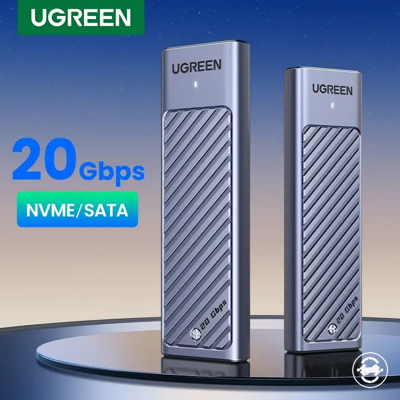
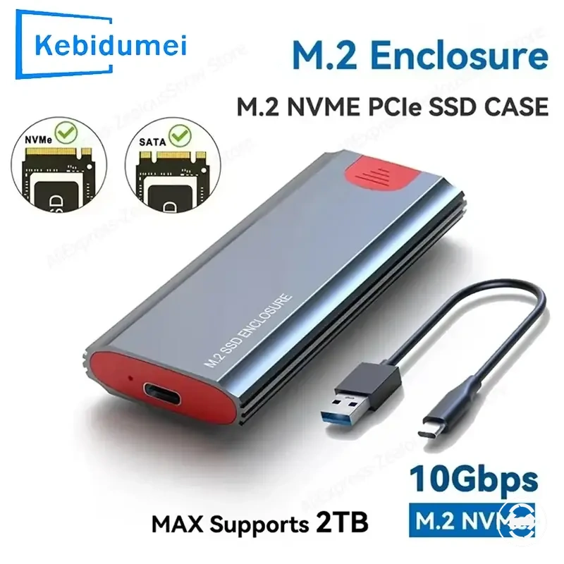
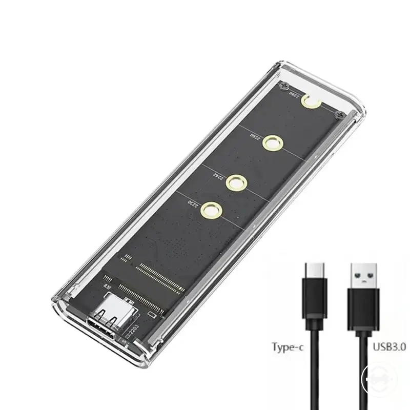
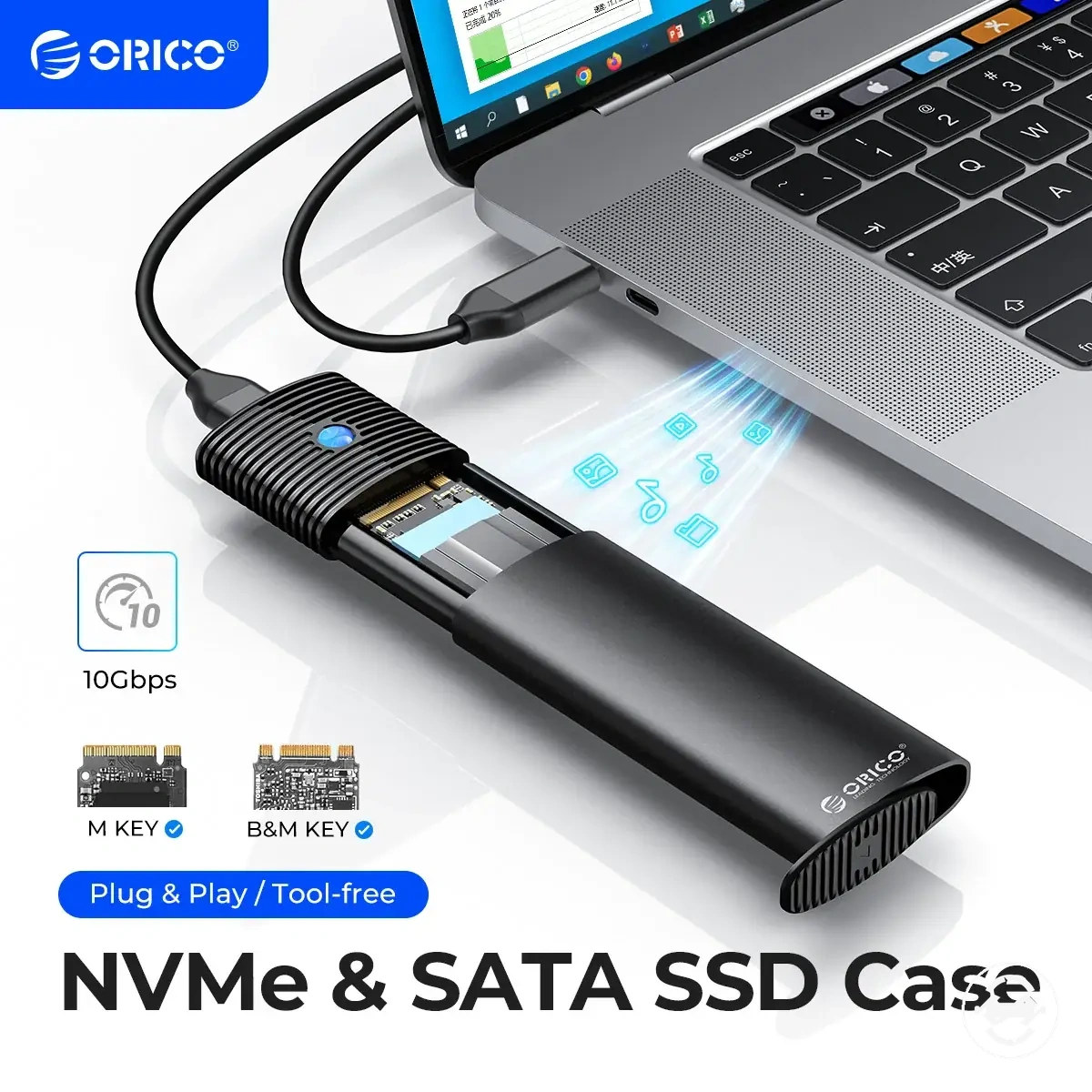
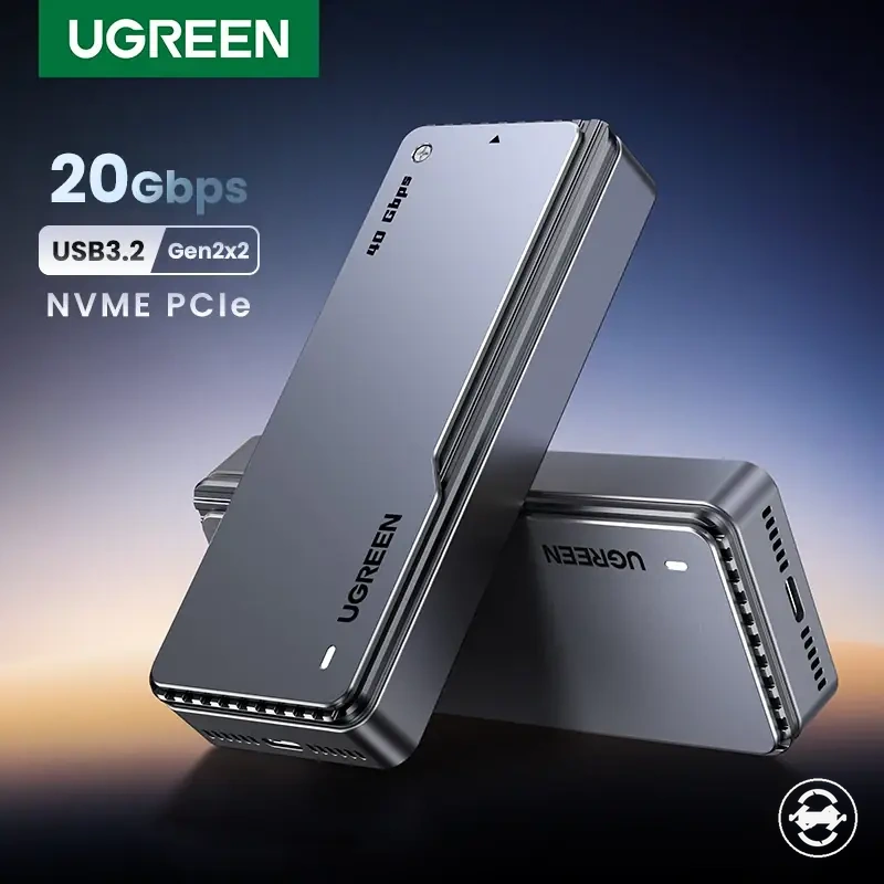
The products below are useful examples for comparing available options. Before buying, check that the compatibility criteria, key features, and product details match your needs.
This chart shows the key checks to prioritize for backup, frequent file transfer, or travel use when buying an enclosure.
M.2 SSD enclosure versus portable external SSD
An M.2 SSD enclosure and a portable external SSD are two storage paths with different setup effort, flexibility, and reliability assumptions. An enclosure path usually makes more sense when the user already owns a compatible internal drive and wants more control over the SSD, enclosure, repairability, and upgrade flexibility. The better choice depends on drive ownership and setup tolerance.
If you already have an M.2 SSD, an M.2 SSD enclosure can reuse that drive, but compatibility risk, host port support, cable behavior, and assembly still need checking. If you want a ready-made drive with simpler setup, a portable external SSD may reduce setup effort and simplify warranty handling. For a deeper storage-path breakdown, see the external SSD comparison.
| Option | Main advantage | Main trade-off | Better fit when |
|---|---|---|---|
| M.2 SSD enclosure | More flexibility, repairability, and upgrade flexibility when using a compatible internal drive. | Requires more setup effort and has more compatibility risk because the drive, enclosure, cable, and host port must align. | You already own an M.2 SSD or want more control over drive choice and enclosure features. |
| Portable external SSD | Simpler ready-made storage path with easier portability and warranty simplicity. | Usually offers less upgrade flexibility because the storage device is bought as a complete unit. | You want plug-and-play simplicity and fewer setup decisions. |
A common misconception is that either option is automatically faster or more reliable. In reality, speed expectations depend on the SSD, enclosure or external SSD design, host port, cable, and workload. Simplicity also depends on configuration, because a ready-made drive reduces setup checks while an enclosure gives more control.
An M.2 SSD enclosure is the more flexible path when compatibility and setup effort are acceptable. A portable external SSD is the simpler path when warranty simplicity and plug-and-play portability matter more.
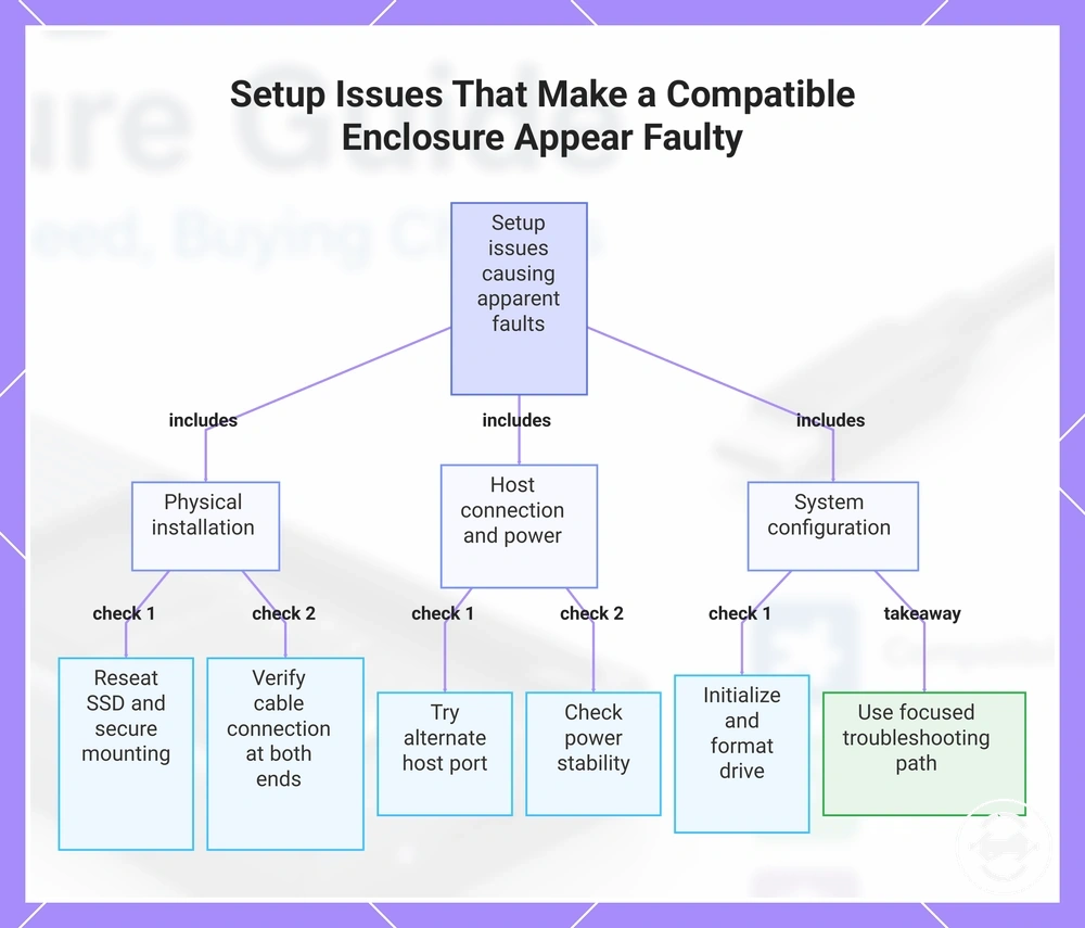
Setup issues that can make a compatible enclosure look faulty
Setup issues can make a compatible enclosure appear faulty when installation, formatting, cable connection, port choice, or detection conditions are incomplete. A not detected symptom does not automatically prove a product defect because drive recognition depends on the full setup path. Apparent faults should be separated from setup conditions first.
Installation problems often start with SSD seating, mounting, or cable connection rather than the enclosure itself. If the drive is not seated correctly or the mounting point does not hold it securely, operating system recognition may fail or become unstable. Port choice and power stability can also affect whether the drive appears consistently. For a focused process, follow the installation steps.
- SSD seating: Symptom: the drive is not detected. Check: reseat the SSD and confirm it is fully inserted. Result: recognition may depend on proper connector contact.
- Mounting: Symptom: intermittent detection or movement inside the enclosure. Check: confirm the SSD is secured at the correct mounting point. Result: loose mounting can make a compatible setup appear unstable.
- Cable connection: Symptom: disconnects or no response. Check: reconnect the cable and verify the connection at both ends. Result: a connection issue may resemble an enclosure fault.
- Port choice: Symptom: the enclosure works on one port but not another. Check: try a suitable alternate host port. Result: the port or host path may influence detection.
- Disk initialization: Symptom: the drive appears in system tools but not as usable storage. Check: confirm whether initialization is required. Result: the enclosure may be working even if the drive is not ready for file use.
- File system formatting: Symptom: the drive is recognized but not accessible as expected. Check: confirm formatting and file system support. Result: formatting condition can affect usability without proving hardware failure.
- Power stability: Symptom: repeated dropouts. Check: review cable, port, and host power conditions. Result: unstable power can cause detection issues.
- Operating system recognition: Symptom: not detected in normal file view. Check: inspect system disk tools before assuming failure. Result: the symptom may reflect configuration or recognition status.
If a compatible enclosure is still not detected after basic seating, cable, port, disk initialization, and file system formatting checks, the next step should be a focused troubleshooting path. This avoids guessing from product claims when the symptom outcome depends on setup and operating system recognition conditions. For detection-specific guidance, use not detected fixes.
Persistent non-detection after basic checks should be treated as a troubleshooting boundary rather than a quick product judgment. Use a focused troubleshooting path before concluding that the enclosure itself is faulty.
This chart shows how physical installation, host connection, and system configuration issues can cause an enclosure to seem faulty, and the key checks to perform before diagnosing a hardware defect.