
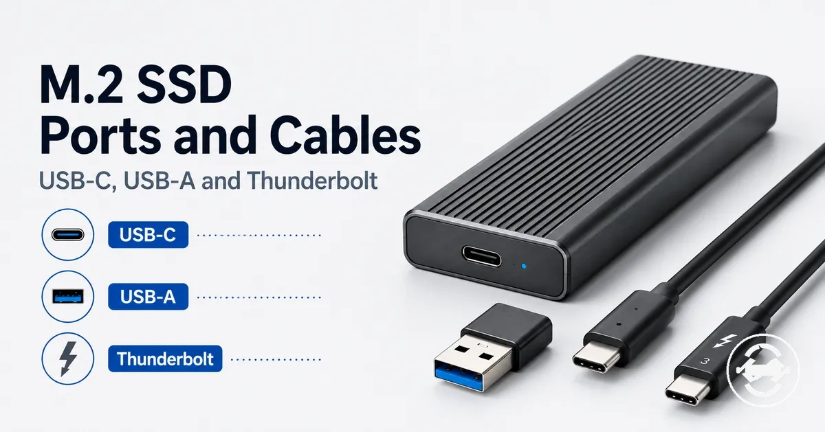
M.2 SSD enclosure ports and cables for USB-C, USB-A, and Thunderbolt
M.2 SSD enclosure ports and cables create the external connection layer between the installed drive and the host device. This connection path can influence usability, compatibility, speed ceilings, and reliability depending on the enclosure, cable, and host port combination. The connector shape and the connection standard describe separate parts of how the enclosure connects.
The same M.2 SSD enclosure may behave differently across computers, adapters, and cables because each connection path can support different capabilities. A USB-C connector may use different protocols, while a USB-A connection may depend on the host port and adapter path. The supported behavior depends on the enclosure, cable capability, and host device pairing. See the M.2 SSD enclosure guide for the wider category context.

M.2 SSD enclosure ports and cables should be evaluated through USB-C, USB-A, Thunderbolt, cable capability, adapter use, and host port support together. USB standards such as USB 3.2 and USB4 describe connection capabilities, but the usable speed ceiling depends on the supported combination of enclosure hardware, cable, and host device.
| Connection element | What it describes | What it can affect | What to verify |
|---|---|---|---|
| Connector shape | The physical plug or port form, such as USB-C or USB-A | Physical connection and cable fit | That the connector matches the enclosure and host port |
| Connection standard | The supported protocol or interface class | Possible speed ceiling and connection mode | The enclosure, cable, and host support the same standard |
| Cable | The connection path between enclosure and host | Data transfer capability and connection stability | Cable capability, rating, and connector type |
| Host port | The computer or device connection point | Compatibility and supported modes | Supported USB or Thunderbolt features |
What the external port and cable control in an M.2 SSD enclosure
The external port and cable control the connection path between an M.2 SSD enclosure and the host device, affecting data transfer, power stability, recognition, and fallback behavior. The enclosure depends on the combined support of the external port, cable, and host rather than the cable alone. Connector shape, protocol support, bandwidth, and signal quality all influence how the connection behaves.
The same M.2 SSD enclosure may behave differently across computers because the host port, cable, and enclosure capabilities can vary. A similar-looking connection may support different protocols or connection modes, which can change the available speed ceiling or recognition behavior. The outcome depends on the supported combination of the enclosure, cable, and host device.
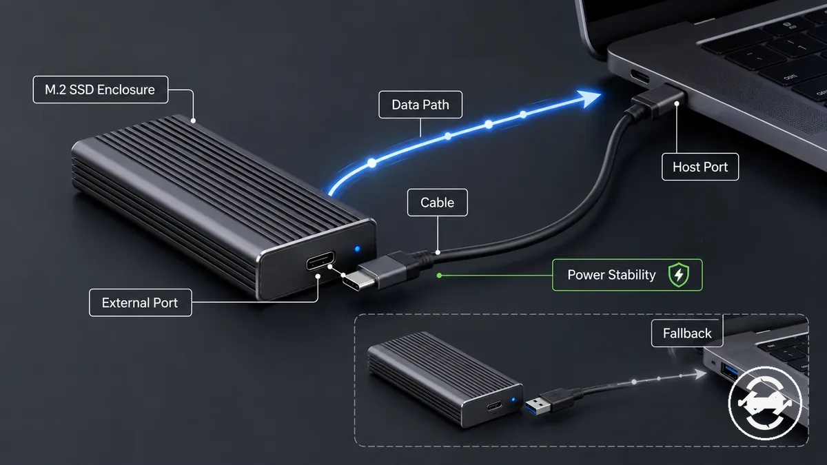
The external port and cable control different parts of the connection path:
- The data path between the M.2 SSD enclosure and the host device, including supported transfer behavior.
- Power stability through the connection, which can influence recognition and consistent operation.
- Protocol negotiation between the enclosure, cable, and host port.
- The available speed ceiling when the enclosure, cable, and host support the same connection mode.
- Recognition behavior when enclosure, cable, or host capabilities do not fully align.
The external connection layer is separate from checking whether the internal SSD fits the enclosure. Full drive-type and physical fit checks belong to compatibility requirements, while this section focuses on the port, cable, and host connection path.
Connector shape versus connection standard
Connector shape is the physical plug form of an M.2 SSD enclosure connection, while connection standard is the supported data protocol or interface capability. Connector shape and connection standard are separate concepts: a connector identifies the physical connection type, and a standard identifies the supported communication method. USB-C and USB-A describe physical connector forms, while protocols such as USB 3.2, USB4, and Thunderbolt describe supported connection capabilities.
Similar-looking ports can support different capabilities, so the visible connector shape does not fully describe the connection behavior. A USB-C-shaped connector may support different protocols depending on host support, enclosure capability, and cable requirement. Checking the port label, protocol support, and cable requirement helps identify the likely connection outcome.
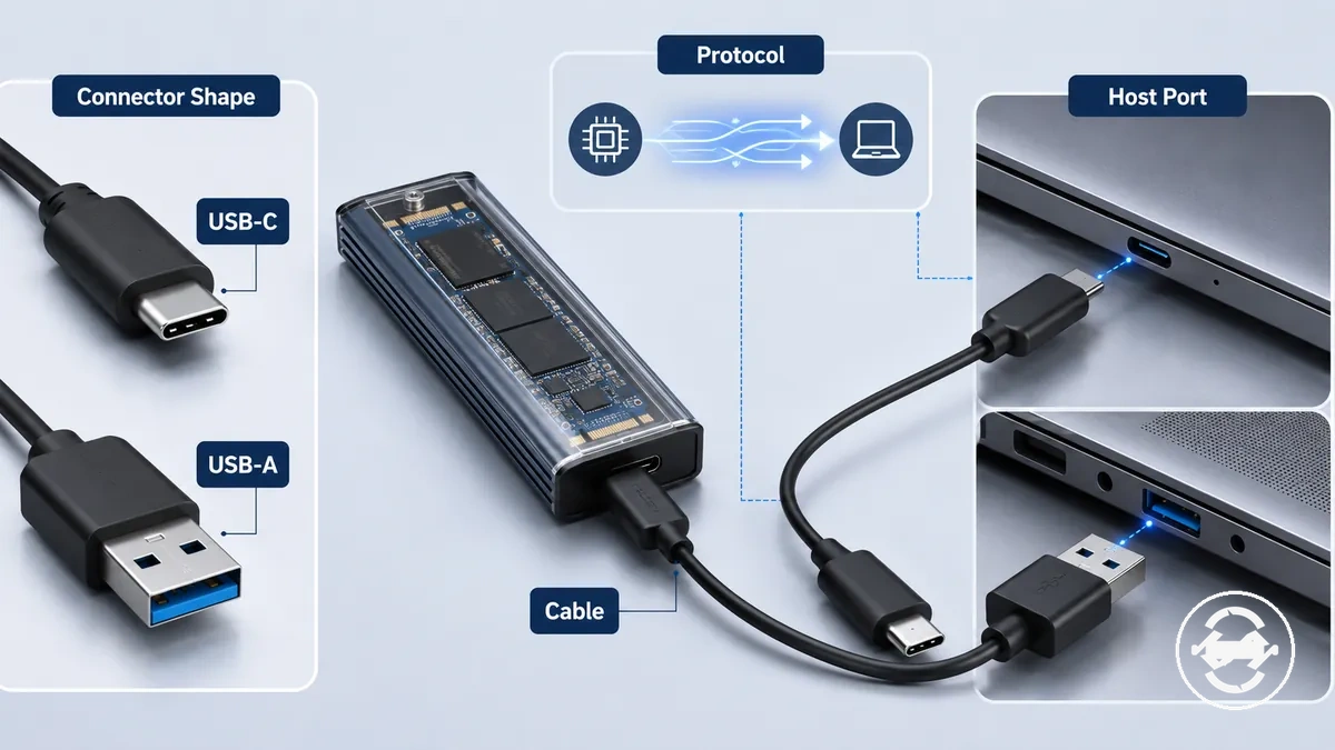
Connector shape versus connection standard can be separated by comparing what each term describes and what information it provides. The comparison below separates physical fit from protocol capability.
| Term | What it tells you | What it does not prove |
|---|---|---|
| Connector shape | The physical plug form, such as USB-C or USB-A | The complete protocol support or connection capability |
| Connection standard | The supported protocol, such as USB 3.2, USB4, or Thunderbolt capability | The final connection outcome without matching host support and cable requirements |
| Port label | The interface information shown by the device | The complete behavior of the connection path by itself |
| Cable requirement | The cable capability needed for a supported connection mode | The result without considering the enclosure and host device |
USB-C as the connector on the enclosure body
USB-C on the enclosure body refers to the physical receptacle used to connect an M.2 SSD enclosure through a cable. The USB-C connector provides a reversible plug orientation and a common connection shape, but it does not automatically define the full protocol support. The supported connection behavior depends on the enclosure controller, host port, and cable capability.
USB-C as the connector on the enclosure body can appear similar across different devices while supporting different connection capabilities. The enclosure controller, host port, and cable requirement can influence the available connection mode. A USB-C shape does not prove the supported standard, because protocol support may vary by the complete connection path.
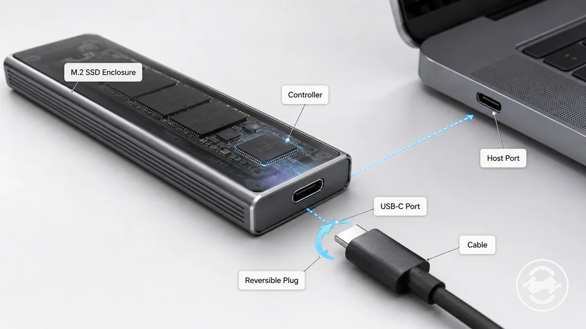
The USB-C connector on an M.2 SSD enclosure separates connector convenience from connection capability:
- Reversible connector: the cable orientation can make physical connection more convenient.
- Cable availability: USB-C cables are commonly used across different enclosure and host setups.
- Protocol support: the supported connection mode can vary based on the controller, host port, and cable capability.
USB-A as a host-side adapter or legacy port
USB-A is a host-side connection path used when a computer provides a USB-A port instead of USB-C. An M.2 SSD enclosure can connect through a USB-C to USB-A cable or adapter, allowing the enclosure to communicate through the computer's legacy port. The available connection behavior depends on the USB standard, host support, and adapter path.
A USB-A host-side port connects the computer and enclosure through a specific cable path rather than changing the enclosure or SSD type. The adapter, cable, and host support can influence the connection mode, bandwidth limit, and power stability. For example, the same M.2 SSD enclosure may connect to an older laptop through USB-A, but the result can vary depending on the supported connection conditions.

USB-A connections separate physical connection from supported capability:
- Host-side port: USB-A provides the computer-side connection point for the adapter or cable path.
- Adapter path: A USB-C to USB-A cable or adapter can connect an enclosure to a USB-A computer port when supported.
- Connection limits: USB standard, cable capability, and power conditions can influence bandwidth and stability.
Thunderbolt and USB-C overlap without identical support
Thunderbolt and USB-C overlap in connector shape, but their protocol support can differ. A Thunderbolt connection may use a USB-C-shaped connector, while the supported connection mode depends on host support, enclosure controller support, and cable support.
A USB-C-shaped port can represent different connection capabilities, so connector shape alone does not define the supported protocol. The Thunderbolt enclosure, USB-C enclosure, host port, and cable must have matching support for the intended connection mode. If the connection parts do not align, a fallback mode may occur with different capability levels.
| Item | What matches | What still needs support |
|---|---|---|
| USB-C shape | The physical connector form used by the enclosure or host port | The supported protocol and interface support |
| Thunderbolt protocol | The supported communication method between compatible devices | Host support, enclosure controller support, and cable support |
| Cable | The connection path between the enclosure and host device | Support for the required connection mode |
| Host port | The computer-side connection point | Supported protocol and fallback mode behavior |
USB 3.2, USB4, and Thunderbolt labels on M.2 enclosure connections
Connection labels on an M.2 SSD enclosure indicate protocol and bandwidth classes that describe supported connection capabilities. USB 3.2, USB4, and Thunderbolt labels act as signals that need to be interpreted with the enclosure controller, host port, and cable rather than as direct measurements of transfer results.
USB 3.2, USB4, and Thunderbolt can represent different connection classes within an M.2 enclosure setup. The label, host support, cable rating, and enclosure controller need to align for the intended connection mode. If these parts do not match, the connection may use a fallback mode with a different speed ceiling.
When a label and the connected components do not fully align, the enclosure may operate through a reduced mode supported by the connection path. Understanding label meaning first helps separate interface capability from observed results. For measured performance factors beyond label interpretation, see real transfer speed.
The table below organizes connection labels by what they can indicate and what still needs to match.
| Label | What it can indicate | What must also match | Safe expectation |
|---|---|---|---|
| USB 3.2 | A protocol label describing a possible connection class | Host support, cable rating, and enclosure controller capability | Indicates a possible mode rather than a guaranteed transfer result |
| USB4 | A protocol label that identifies a supported connection class | Compatible host port, cable support, and enclosure support | Requires matching components for the intended connection mode |
| Thunderbolt | A protocol label associated with supported connection paths | Host support, enclosure controller support, and cable support | Connector appearance alone does not define the supported capability |
10Gbps, 20Gbps, and 40Gbps interface limits
10Gbps, 20Gbps, and 40Gbps describe interface ceilings rather than guaranteed sustained transfer rates. These values represent bandwidth classes that define a possible connection ceiling when the enclosure support, cable rating, and host capability match. The interface ceiling describes the connection limit, while the practical outcome depends on the complete connection path.
A connection may fall back to a lower negotiated mode when one part of the setup does not match the interface ceiling. For example, an enclosure with a higher rated limit may use a reduced mode if the host port, cable rating, or enclosure support cannot provide the same capability. This weak link can reduce the available connection ceiling without changing the interface label itself.
The table below separates interface ceilings from the requirements and conditions that can reduce the supported mode.
| Interface ceiling | Matching requirement | What can reduce it |
|---|---|---|
| 10Gbps | Matching host capability, cable rating, and enclosure support | Lower supported mode from a host, cable, or enclosure mismatch |
| 20Gbps | Compatible connection support across the enclosure and host path | Fallback caused by unsupported components or connection limits |
| 40Gbps | Matching interface support between host, cable, and enclosure | Host capability, cable rating, or enclosure support limitations |
Backward compatibility and fallback connection modes
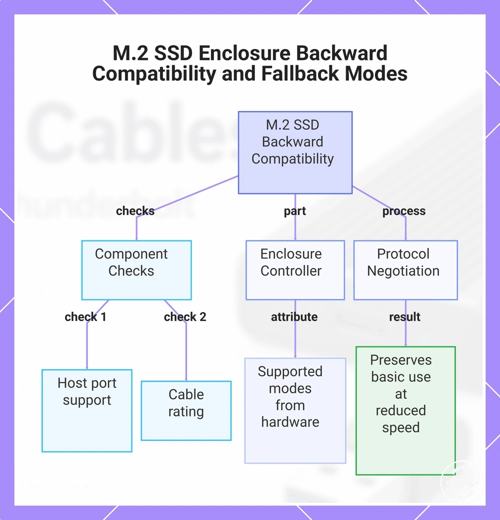
Backward compatibility allows an M.2 SSD enclosure connection to use a fallback mode when the enclosure, cable, and host do not share the highest supported standard. This fallback mode is a form of protocol negotiation that can preserve basic use through a supported lower mode, while the connection may operate with reduced speed or fewer available features.
A working connection can still operate below the enclosure’s expected speed ceiling when the host port, cable rating, or enclosure controller supports a lower negotiated mode. For example, a cable with limited support or a host port with different capabilities may allow the enclosure to function while using a reduced speed mode.
Backward compatibility can be understood by separating basic use from full capability:
- Host support: confirm that the host port supports the intended connection mode.
- Cable rating: check whether the cable supports the required connection capability.
- Enclosure controller: consider the supported modes available from the enclosure hardware.
- Protocol negotiation: understand that mismatched components may result in a lower supported mode.
This chart shows the main factors and checks for understanding backward compatibility in M.2 SSD enclosures, including hardware checks, enclosure controller support, and protocol negotiation outcomes.
Host port, cable, and enclosure support as a shared limit
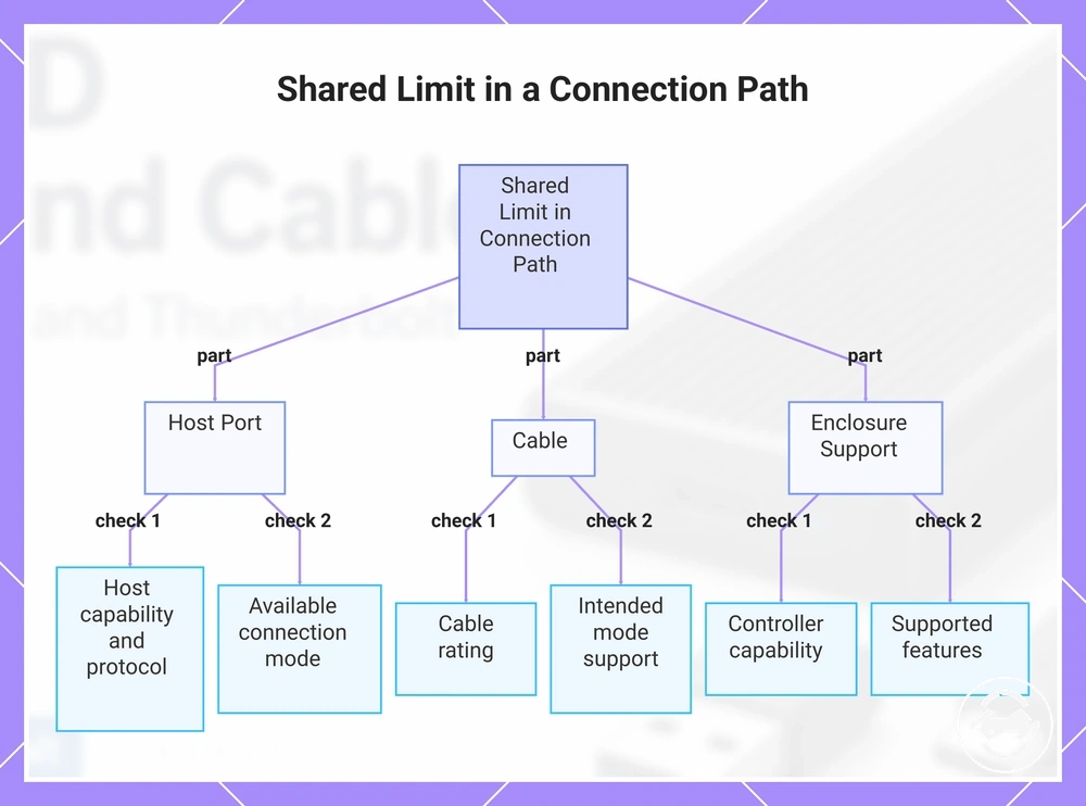
The connection path has a shared limit because the host port, cable, and enclosure support must work together to determine the usable mode. The least capable supported part in the path can influence the negotiated mode, including protocol support, bandwidth rating, and power stability. Compatibility depends on how these parts work together rather than on a single component alone.
A laptop, desktop, hub, dock, or adapter can provide different connection conditions because the host port and related components may support different capabilities. The cable and enclosure controller also affect whether the connection uses the expected mode or a lower supported mode. A mismatch in support can change the available connection ceiling or detection behavior.
Compatibility requirements help evaluate the external connection path by checking the host port, cable, and enclosure support together. Protocol support, bandwidth rating, and negotiated mode can vary by configuration, so compatibility is not only a simple yes-or-no condition.
The shared limit principle helps explain why a connection can have a supported ceiling that differs from observed results. The final outcome depends on the complete connection path, and factors affecting the ceiling can also influence real transfer speed.
The checklist below evaluates the shared limit across the connection path:
- Host port: Check host capability, protocol support, and the available connection mode.
- Cable: Review cable rating and whether it supports the intended negotiated mode.
- Enclosure support: Consider enclosure controller capability and supported connection features.
This chart shows the three components that form the shared limit in a connection path and the key checks for each to determine the usable mode.
Cable and adapter choices for reliable enclosure use
Choosing a cable or adapter for reliable enclosure use requires matching the cable path, connector fit, and data capability with the M.2 SSD enclosure and host port. A suitable cable choice depends on the connection requirements rather than only the plug shape, because cable rating, length, and physical fit can affect detection, stability, and supported connection behavior.
A USB-C to USB-C cable can connect an enclosure with a USB-C enclosure port to a compatible USB-C host port, while a USB-C to USB-A cable or adapter can provide a different host-side connection path. The cable and adapter should match the enclosure port and host port so the supported mode can be used. A bundled cable may be enough when its capability matches the setup, while a replacement cable may be worth checking when cable capability or connection behavior is uncertain.
Cable and adapter choices can be evaluated through connector match, data support, cable rating, length, and physical fit. A data-capable cable with suitable rating helps align the enclosure, adapter, and host connection path, while a poor fit or unknown capability can affect stability.
Reliable enclosure use depends on selecting a cable and adapter that match the enclosure port, host port, and intended use case. Decision signals such as connector fit, data capability, cable rating, length, and replacement need help determine whether an included cable is suitable or whether another cable path should be considered.
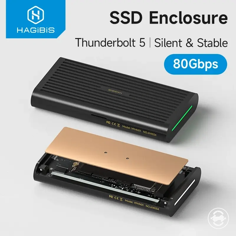
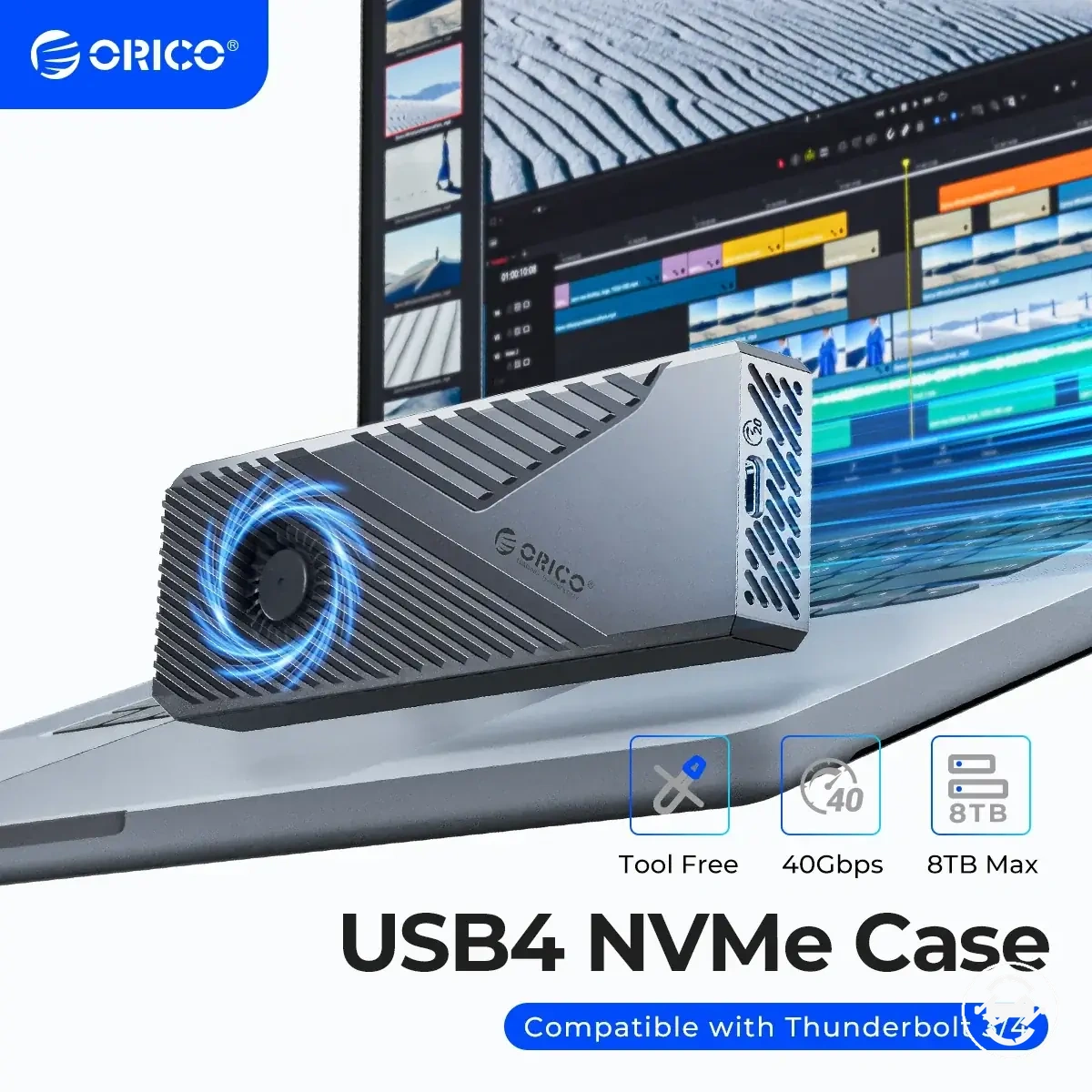
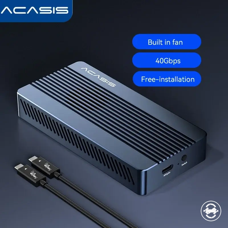
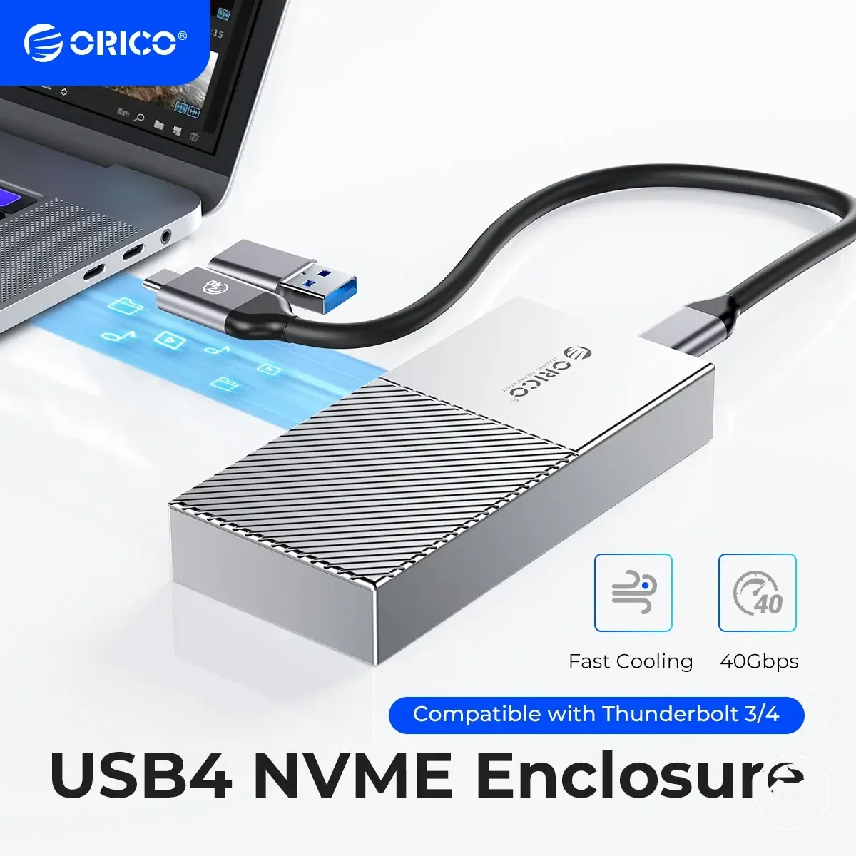
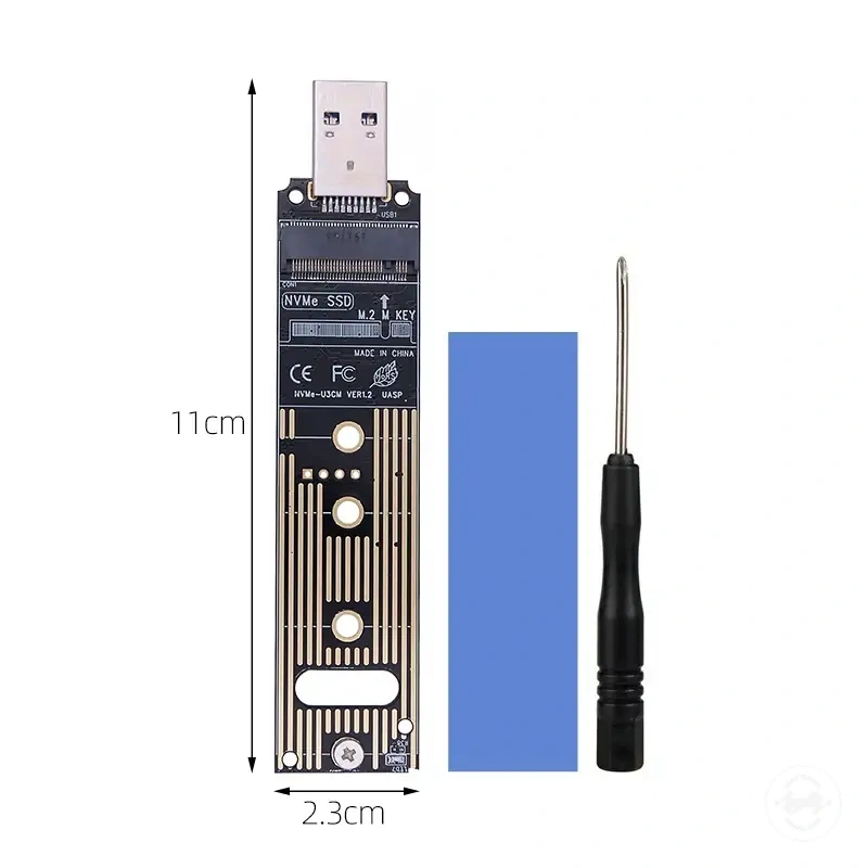
The products below are useful examples for comparing available options. Before buying, check that the compatibility criteria, key features, and product details match your needs.
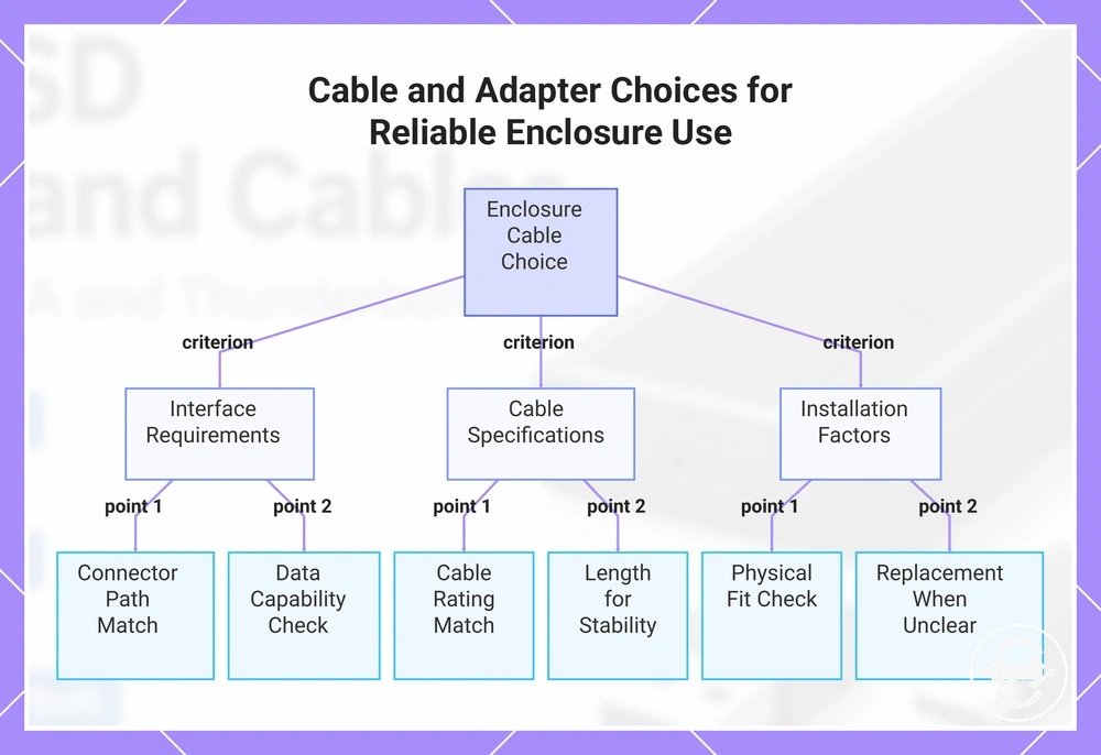
- Connector path: Confirm the cable or adapter matches the enclosure port and host port.
- Data capability: Check that the cable is a data-capable cable and supports the required connection mode.
- Cable rating: Match the cable rating with the enclosure and host requirements.
- Length: Consider length as part of connector fit and connection stability.
- Physical fit: Check that the cable path works with the available ports and setup.
- Replacement need: Consider a replacement cable when bundled cable capability is unclear.
This chart summarizes the essential checks for selecting a cable or adapter that matches the enclosure port, host port, and intended use case.
USB-C to USB-C cables and USB-C to USB-A cables
USB-C to USB-C and USB-C to USB-A cables are chosen by matching the cable path between the enclosure port and the host device. USB-C to USB-C connects a USB-C enclosure port to a compatible USB-C host device, while USB-C to USB-A connects the enclosure to a host device with a USB-A port. The cable end shape and data support should both be checked before selecting the connection path.
A modern USB-C laptop may use a USB-C to USB-C cable when the enclosure port and host device support that connection path. An older USB-A desktop may require a USB-C to USB-A cable or an adapter depending on the available host-side connector. The expected speed ceiling and connection behavior depend on data support, adapter need, and the supported capability of the cable path.
The comparison below separates cable path selection by host fit and capability checks.
| Cable path | Host fit | Capability check | Typical reason to use |
|---|---|---|---|
| USB-C to USB-C | Fits a host device with a compatible USB-C port | Check data support and supported connection capability | Connects an enclosure port to a matching USB-C host path |
| USB-C to USB-A | Fits a host device with a USB-A port | Check data support and adapter need where required | Connects an enclosure port to a legacy host-side connector |
Data-capable cables versus charge-only cables
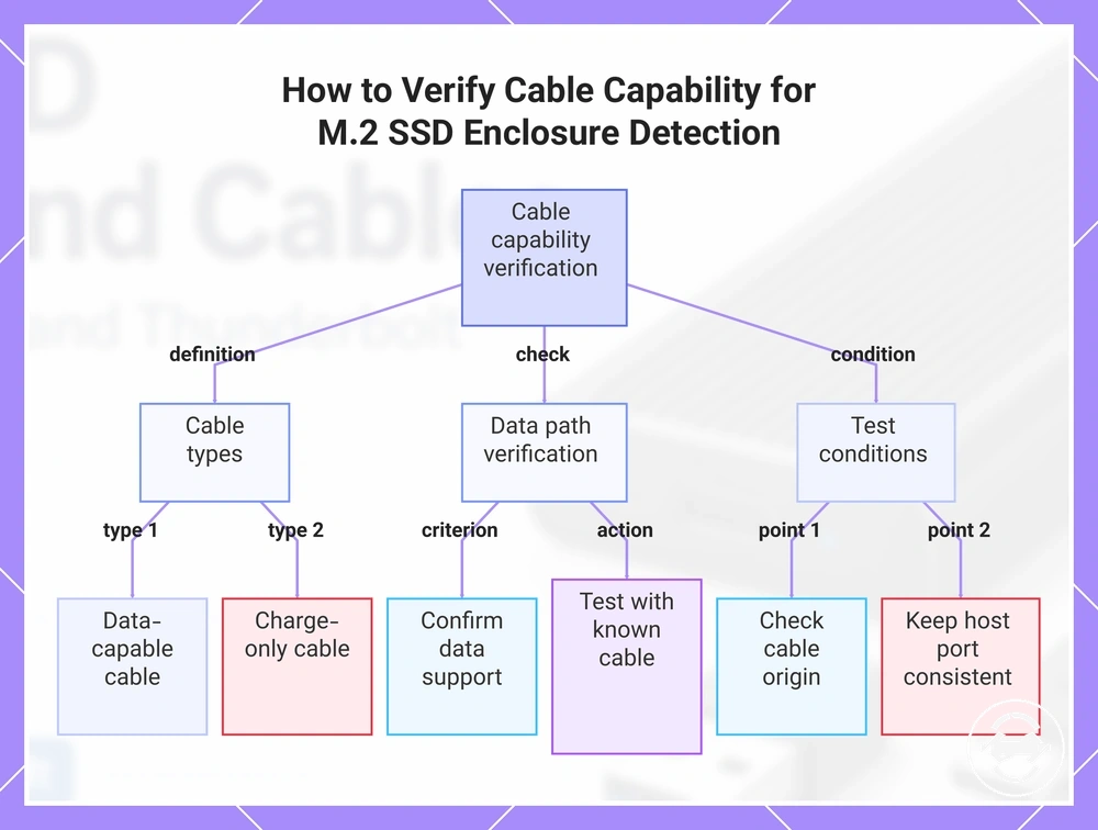
A data-capable cable provides a usable data path for an M.2 SSD enclosure, while a charge-only cable can provide power behavior without enabling storage data access. When a cable is truly charge-only, the enclosure may not have the data connection required for detection. Cable capability should be considered as one possible factor when the enclosure is not detected.
A clean verification path is to test the enclosure with a known data-capable cable before changing other parts of the setup. A bundled cable may provide data support, but an unknown cable rating or cable type can make detection results harder to interpret. Keeping the host port consistent while testing helps separate cable capability from other connection factors.
The checklist below verifies cable capability without assuming the cable is the only possible cause:
- Cable origin: Check where the cable came from and whether its intended use is known.
- Data support: Confirm that the cable provides a usable data path for the enclosure.
- Known cable: Test with a known data-capable cable to compare detection behavior.
- Host port: Avoid changing multiple variables at once during the verification process.
This chart shows cable types and the key verification steps to determine if a cable's data capability is causing an enclosure detection failure.
Detachable, bundled, and replacement cable considerations
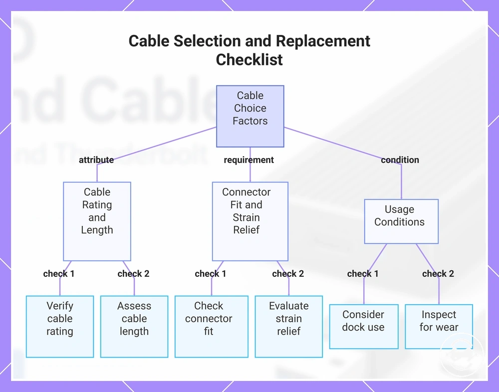
Bundled cable, detachable cable, and replacement cable choices can matter when the enclosure setup changes or when cable condition affects connection behavior. A bundled cable may be suitable when its included rating, length, and connector fit match the enclosure and host setup. A replacement cable may be considered when the cable source, supported standard, or physical condition is uncertain.
Replacement cables should match the enclosure connector fit and supported standard rather than only the visible plug shape. Cable rating, length, and strain relief can influence connection stability, while conditions such as dock use or a worn connector may contribute to intermittent disconnects in some setups.
The checklist below organizes practical cable replacement criteria:
- Cable rating: Check whether the cable supports the required connection capability for the enclosure.
- Length: Consider length as part of the cable path, physical setup, and stability.
- Connector fit: Confirm the cable matches the enclosure port and host connection path.
- Strain relief: Consider connector support and cable construction around connection points.
- Dock use: Consider whether a dock changes the connection path or supported behavior.
- Worn connector: Inspect for wear when intermittent disconnects occur.
This chart shows the main factors to check when selecting or replacing a cable for an enclosure setup.
Cable-related detection and connection symptoms
Cable-related symptoms are diagnostic signals that can point to the cable, adapter, host port, enclosure, or another part of the connection path. A symptom such as not detected, intermittent disconnects, slow fallback, or unstable transfer does not prove a single cause by itself. The next check should separate cable-related conditions from broader enclosure or host configuration factors.
When a connection issue appears, checking the cable, adapter, port, enclosure, and host separately can help identify the likely condition. A cable rating, connector fit, or negotiated mode may influence detection or reliability, but similar symptoms can come from other parts of the setup. This makes a step-by-step check more useful than assuming the cable is the cause.
Cable-related symptoms can appear in different patterns depending on the connection path. A not detected issue may relate to cable support, host port behavior, or enclosure communication, while intermittent disconnects may involve connector fit or adapter reliability. Slow fallback and unstable transfer can also indicate that the connection is operating in a reduced mode.
| Symptom | Likely connection issue | Check | What it means |
|---|---|---|---|
| Not detected | Cable, adapter, host port, or enclosure connection condition | Check cable support, connector fit, and host port behavior | The symptom indicates a connection issue that needs further isolation |
| Intermittent disconnects | Connector fit, cable condition, adapter path, or connection stability | Check cable connections and related components | The connection may not remain stable under the current setup |
| Slow fallback | Cable rating, negotiated mode, or supported connection limit | Check the supported cable and connection path | The setup may be operating in a reduced mode |
| Unstable transfer | Cable, adapter, host port, or enclosure communication condition | Review the connection path and possible limiting factors | The symptom suggests additional checking is needed |
Slow fallback symptoms may need a more focused review of speed-related conditions after cable and port checks. For cases where reduced performance remains unclear, see slow transfer troubleshooting for the dedicated speed path.
Intermittent disconnects may require further separation between cable, adapter, and connection stability factors. If disconnecting continues after these checks, see disconnecting problems for the dedicated stability path.